





 Nederlands
 Italiano
 Português
 Română
 Español
 Ελληνικά
 Polski
 Türkçe




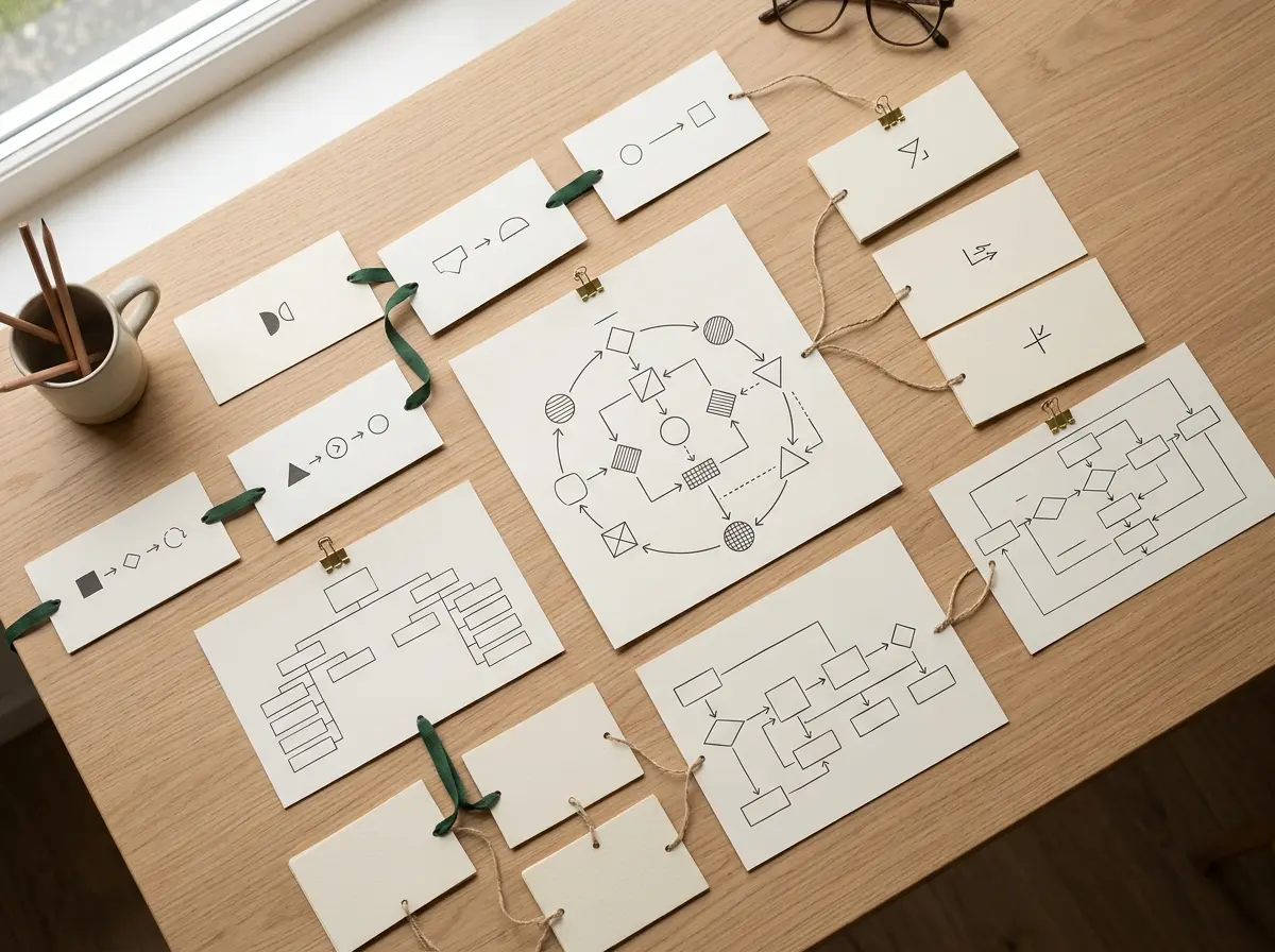
Somewhere around the fourth box, the whole thing turns hostile. A process map that looked fine ten minutes ago now has an arrow looping the long way around a decision diamond, and dragging a shape two inches to the left detaches three connectors that were fine a second ago. Most people hit this point and assume Microsoft Visio is broken.
It usually isn’t. The connector behaviour that ruins flowcharts comes down to one distinction almost nobody explains up front: gluing a connector to a whole shape versus gluing it to a fixed spot on that shape. Get that one thing straight and about 80% of the “why is this arrow doing that” moments disappear.
So this guide skips the shape-placement basics you can find in any menu. It spends the time on the part that actually makes people quit: glue types, why connectors jump, how AutoConnect decides routing, and then swimlanes in the second half.
Why the usual flowchart advice falls apart
Most walkthroughs are honest but incomplete. They show you how to drag a shape from the Shapes pane, type a label, and connect two boxes. All correct. Then the guide ends, right at the moment the reader’s real trouble starts.
The gap is connector behaviour. Guides treat it as an advanced topic, so the beginner who hits it assumes the tool is defective. Microsoft’s own basic flowchart walkthrough does cover the mechanics of adding shapes and connectors, but the why does my arrow keep detaching question sits a layer deeper than where most tutorials stop.
Here’s what gets skipped. Visio has two ways a connector can attach to a shape, and they behave completely differently when you move things around. Nobody tells you which one you’re using, and the default can flip depending on how you drew the connector.
Glue points versus dynamic connections
This is the whole game, so it’s worth slowing down.
When you glue a connector to a shape in Visio, you’re doing one of two things. Either you’re attaching it to a specific connection point (a little blue X on the shape’s edge) or you’re attaching it to the shape as a whole. The first is called static glue. The second, dynamic glue.
Static glue pins the arrow to one exact spot. Move the shape and the connector stays locked to that point, even if that means the arrow now crosses awkwardly over the box to reach it. That’s the “why is my connector routing around the shape” problem in one sentence.
Dynamic glue attaches to the shape, not a point on it. Move the box and Visio recalculates the shortest sensible path, sliding the attachment point around the perimeter on its own. That’s what you want for most flowchart work.
Why do connectors “jump” when you rearrange boxes? Almost always a mix of the two on the same diagram. Some arrows are pinned to points, some to shapes, and the diagram reflows unevenly. Standardising on dynamic glue is the single biggest fix, and it’s the piece the competitor guides leave out entirely.
How AutoConnect actually decides routing
AutoConnect is the feature that shows blue directional arrows around a shape when you hover near it. Click one, and Visio drops a connected shape in that direction, glued and routed automatically.
It’s genuinely useful once you know its logic. AutoConnect connects to the nearest available connection point on the target, using dynamic glue by default. So if your arrows keep landing somewhere you didn’t intend, it’s usually because the nearest point wasn’t the one you had in mind – not because Visio ignored you.
A few working habits keep AutoConnect predictable:
- Leave enough space between shapes. Cramped boxes give AutoConnect fewer sensible points to choose from, and routing gets ugly.
- Use the arrows to add shapes when possible. A shape dropped via AutoConnect arrives pre-glued dynamically, which saves you the manual gluing step and the errors that come with it.
- If a connector routes the long way, drag the shape slightly. Because the glue is dynamic, the path recalculates instantly, and you can nudge it into a clean line in a second or two.
“The connectors aren’t fighting you. They’re following glue rules you can’t see until you know to look for them.”
Microsoft’s process-visualisation guide is a decent reference for the routing options once you understand this baseline. But the baseline is the thing. Learn glue first, everything downstream makes sense.
How to make a flowchart in Visio: a clean connector workflow
Point is, a repeatable order of operations prevents most of the mess. Here’s a sequence that holds up.
- Open a visio flowchart template rather than a blank page. The Basic Flowchart template loads the right stencil and sets sensible connector defaults from the start.
- Place your first shape, then use AutoConnect arrows to add the next few. Every shape added this way comes dynamically glued.
- For connections you draw manually, watch for the green circle (dynamic), not the green square (static).
- Rearrange freely. Because glue is dynamic, boxes can move and arrows follow.
- Only switch to static glue at the very end, and only for the rare arrow you want anchored to an exact port.
If you’re comparing tools before committing, EdrawMax’s Visio flowchart overview walks the same territory from a different angle, which can help confirm you’re not missing a setting specific to your version.
Building swimlanes without the same fight
The second half of real flowchart work is swimlanes, and this is where people re-create the connector pain by doing it the hard way. They draw rectangles for lanes, label them, and then wonder why shapes don’t stay inside a lane when moved.
Don’t hand-draw lanes. Use the Cross-Functional Flowchart template. It gives you container lanes that are aware of the shapes inside them, so a shape assigned to a lane moves with that lane and stays organised.
Here’s the workflow for a cross functional flowchart visio users can actually maintain:
- Start a new file from the Cross-Functional Flowchart template. Choose horizontal or vertical orientation when prompted.
- A swimlane frame appears with placeholder lanes. Rename each lane header with the role or department it represents.
- Drag flowchart shapes into the lane they belong to. The lane recognises the shape as a member.
- Add or remove lanes using the Cross-Functional Flowchart tab on the ribbon, not by copying rectangles.
- Connect shapes across lanes the same way as before, using dynamic glue, so cross-lane arrows reroute cleanly when lanes shift.
The payoff is that a swimlane diagram visio built this way survives editing. Reassign a step from one team to another by dragging it to a different lane, and the structure holds. EdrawMax’s cross-functional flowchart guide covers the lane-management ribbon in more depth if you want a second reference on the container behaviour.
| Approach | Lanes aware of shapes? | Survives rearranging? | Best for |
|---|---|---|---|
| Hand-drawn rectangles | No | Poorly | Never, really |
| Cross-Functional template | Yes | Yes | Any multi-role process |
| Basic Flowchart template | No lanes | Yes for connectors | Single-actor processes |
Troubleshooting the moments that make people quit
A connector won’t detach from an old shape. That one is statically glued to a point that no longer suits the layout. Select the connector, drag the endpoint off, and re-drop it so the green circle appears for dynamic glue.
Arrows cross straight through shapes. Usually a spacing problem plus static glue. Widen the gap between boxes, confirm the endpoints are shape-glued, and the router will find a clean path around.
Shapes won’t join a swimlane. You’re probably on the Basic Flowchart template with hand-drawn lanes, which have no container logic. Rebuilding on the Cross-Functional Flowchart template fixes this at the root rather than fighting it shape by shape.
Everything reflows badly after one small move. That’s mixed glue across the diagram. Tedious to fix, but worth it – select the connectors and standardise them to dynamic before you finalise.
FAQ
Why does my Visio connector move when I move a shape?
Because it’s dynamically glued to the shape, which is the desired behaviour. Dynamic glue lets Visio recalculate the path so arrows stay clean as you rearrange. If a connector instead stays pinned to one awkward spot, that one is statically glued to a point and needs re-gluing to the shape.
What’s the difference between static and dynamic glue in practice?
Static glue locks a connector to one exact connection point on a shape. Dynamic glue attaches it to the shape overall and lets the endpoint slide around the edge as needed. For flowcharts you’ll edit, dynamic glue is the default you want, and it’s the core of most useful visio connector tips.
Should I draw swimlanes myself or use a template?
Use the Cross-Functional Flowchart template. Hand-drawn lane rectangles have no awareness of the shapes inside them, so nothing stays organised when you move things. Template lanes are containers that keep assigned shapes grouped.
Can I turn a basic flowchart into a swimlane diagram later?
It’s possible but clumsy, since the basic template has no lane containers to add shapes into. Starting from the cross-functional template is far less work than retrofitting lanes onto an existing diagram.
Which Visio edition do I need for cross-functional flowcharts?
The Cross-Functional Flowchart template ships with the standard desktop Visio flowchart stencils, so most current editions include it. Confirm your specific edition’s feature list before buying if swimlanes are the reason you’re purchasing.
Wrapping up
Learning how to make a flowchart in Visio that doesn’t fight back is mostly about seeing what was invisible: the glue rule behind every connector. Standardise on dynamic glue, let AutoConnect place pre-glued shapes, and build swimlanes from the Cross-Functional Flowchart template instead of drawing lanes by hand. Do those three things and the software stops feeling broken.
And if you still need a genuine, correctly-licensed copy of Visio or the wider Office suite to do this on, buying the right edition once beats fighting an activation loop later.